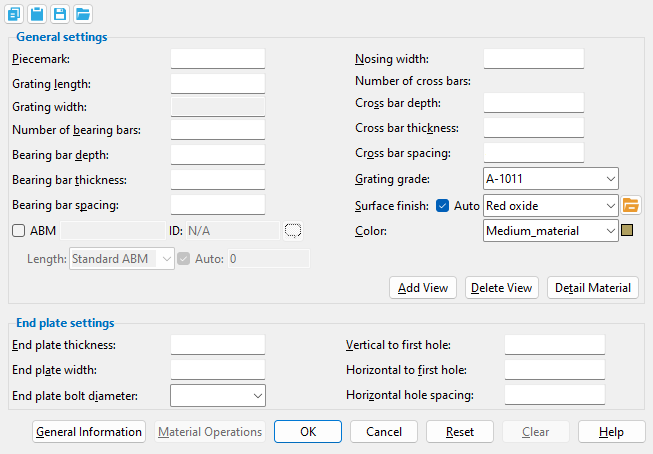
The Grating Tread Material window
- General Overview
- Tips and Tricks
- Related Tools
![]() Copy, Paste, Save, Load buttons:
Copy, Paste, Save, Load buttons:
- The position of these "form" buttons on the window tells you what settings they apply to. Click here for more information.
- You can
 Copy the settings on this window, then
  Paste those settings to a different edit window of the same type.
- You can
 Save the settings on this window to a file stored in a global folder that is used by your current version of SDS2. Give the file a name that will help other users identify its purpose. You can
  Load a saved file to replace the settings on this window (except Piecemark) with the settings that are stored in the file you select.
- When editing multiple windows at the same time, Paste and Load replace mixed entries to a single field with a single entry. Copy and Save ignore fields with mixed entries, treating them as if they have no entry or do not exist.
------ General settings ------
Piecemark: Blank or any character string (up to 61 characters). This is the submaterial piecemark.
If this field is left blank, then when this material is generated (after you press "OK"), SDS2 piecemarking looks for materials in the current Job that are physically identical to this material and assigns to this material the same mark assigned to those materials. If no matching materials are found, piecemarking assigns this material a piecemark using the appropriate material mark prefix listed in Home > Project Settings Fabricator > Member and Material Piecemarking > the "Prefixes" tab.
Any character string that you enter must be unique. Validation routines prevent you from entering a piecemark that has already been assigned to materials. A piecemark entered here only applies if the material you are adding is unique -- if the material is exactly the same as previously added materials, the new material gets the piecemark of those previously added materials. On the other hand, if you are editing the material, all materials that are exactly like the material are re-assigned the unique mark you enter when the material is generated (after you press "OK"). The piecemark you enter remains a system piecemark , which means that it may be changed if you later edit a material just like this one and give that material a different piecemark.
Note: A submaterial mark is not yet assigned when this window opens for an add material. A piecemark is shown when you Edit Material or Review 2D Items. For the current quantity of materials assigned this piecemark, see the "Current quantity" listed on this material's General Information window.
Report Writer: MemberMaterial.Material.MinorMark
Advanced Selection: MinorMark
Grating length: The distance from outside edge-to-outside edge of the grating tread along its X material axis.
Note: Length is added to/subtracted from the end of the grating tread that is opposite to the first point added. Changing this distance may adjust the "Number of cross bars" while keeping their thickness and spacing the same.
Grating width: read-only. The distance from outside edge-to-outside edge of the grating tread along its Y material axis.
Note: Grating width is calculated based on the following formula:
[ ( number of bearing bars - 1) * ( bearing bar spacing ) ] + bearing bar thickness + nosing width
This means that if you change the "Number of bearing bars" or "Bearing bar spacing" or "Bearing bar thickness" or "Nosing width", the grating tread width will be recalculated.
Number of bearing bars: The total number of bars that are parallel with the grating tread's X material axis.
Note: Changing the number of bearing bars that is entered here changes the "Grating width". Each of these bars will be slightly shorter than the "Grating length" is long.
Report Writer: XXXXXX.NumberOfStringersInGrate
Advanced Selection: NumberOfStringersInGrate
Bearing bar depth: The distance between the top (walking surface) and bottom edges of the bearing bars.
Report Writer: XXXXXX.BearingBarWidth
Advanced Selection: BearingBarWidth
Bearing bar thickness: The thickness of the bearing bars.
Note: Changing the bearing bar thickness that is entered here also changes the "Grating width".
Fabricator Setup: Add bearing bar thickness to grating tread description (Member Detailing Settings)
Report Writer: XXXXXX.BearingBarThickness
Advanced Selection: BearingBarThickness
Bearing bar spacing: The distance measured from center-to-center of the bearing bars.
Note: Changing the bearing bar spacing that is entered here also changes the "Grating width".
Report Writer: XXXXXX.BearingBarSpacing
Advanced Selection: BearingBarSpacing
Nosing width: The width of the nosing plate measured from the outside edge of the grating tread to the near edge of the nearest bearing bar.
Note: Changing the width of nosing that is entered here also changes the "Grating width".
Report Writer: XXXXXX.NosingWidth
Advanced Selection: NosingWidth
Number of cross bars: (read-only). This is the number of bars that are parallel with the grating tread's width.
Note: To change the number of cross bars, you need to adjust the "Grating tread length" or change the "Cross bar spacing".
Cross bar depth: (data only) The distance measured perpendicular from the top edge (walking surface) of the cross bars to the bottom edge of the cross bars.
Note: The cross bar depth is not shown 3-dimensionally in the model.
Report Writer: XXXXXX.CrossBarWidth
Cross bar thickness: The thickness of the cross bars.
Report Writer: XXXXXX.CrossBarThickness
Cross bar spacing: The distance measured from center-to-center of the cross bars.
Note: Changing the cross bar spacing may cause the "Number of cross bars" to be recalculated. For instance, if you were to increase the cross bar spacing, the "Number of cross bars" might decrease since the "Grating tread length" would remain the same.
Report Writer: XXXXXX.CrossBarSpacing
Grating grade: The material grades that you can select in this list box ( ![]() ) come from Home > Project Settings Job > Grating Grades.
) come from Home > Project Settings Job > Grating Grades.
Bill of material: Steel Grade
Status Display: Member status > Steel grade
Advanced Selection: MaterialGrade
Parametric module: MaterialGrade
Surface finish: None or Sandblasted or Red oxide or Yellow zinc or Gray oxide or Blued steel or Galvanized or Duplex Coating or Undefined 1 or Undefined 2 or Undefined 3 or Red oxide 2 or Any user added surface finish. This affects the colors of Solid members on erection views in the Drawing Editor . This also sets the color when Output material color is set to Surface finish for a VRML Export or a DWG/DXF Export. The Color (not Surface finish) sets the color of this material in Modeling .
| sand blasted | red oxide | yellow zinc | user surface finish 1 |
| gray oxide | blued steel | galvanized | user surface finish 2 |
To assign a different surface finish, you can drop-down the current surface finish and select the one you want, or you can press the
Auto ![]() or
or ![]()
If this box
is checked, the material surface finish follows what is set on the member level.
If the box
is not checked, the material surface finish can be changed to whatever is available in the list of surface finishes. If the surface finish changes from what the member level has set, the auto checkbox will be unchecked automatically. When the auto check box is unchecked, the member edit window shows an information tag which notifies the user that an attached material is not following what was set on the member level.
Note 1: Submaterial piecemarks can be split apart by surface finish. All surface finishes that do not have the Break Marks Material checked on can be applied to any like material with out the material splitting. If the Break Marks Material is checked on then only like materials with that specific surface finish can have the same piecemark, and because the submaterial marks differ so would the member's piecemark.
Note 2: When exporting a KISS file using "model" as the Data source surface finish data on the materials are compiled into the KISS download as follows, with a few exceptions (G=galvanized, N= none or sandblasted, P= others). Those exceptions are:
If the box for Finish routing in KISS export setup is set to a user routing
If the user has adjusted the Abbreviation for any of the default provided surface finishes
If you are using a user added surface finish
In these cases you will get what is provided in either the User routing, or the abbreviation field. For other exports it will always provide the abbreviation in the 'surface finishes' settings page.
Tip 1: Surface area is reported on the General Information window -- and this can be used to estimate the amount of coating required and its cost.
Tip 2: Changing Steel grade, Color, and Surface finish do not cause the plate to be regenerated. This means that, if you change those settings only, material fit operations such as a Fit Exact may optionally be preserved.
Report Writer: MemberMaterial.Material.SurfaceFinish
Setup: Surface Finish Settings
Color: A predefined color or a custom color. This is the approximate color of the grating tread when it is displayed in one of the three solid forms.
The predefined colors are set up on the Predefined Colors window. The color swatch next to the list box (
) displays the color that is selected.
Select 'Custom Color' (last choice on the list) to launch your operating system's color picker and define any color you like.
Tip 1: Different colors may be assigned to materials that have the same submaterial piecemark.
Tip 2: Changing "Color" and "Surface finish" do not cause the material to be regenerated. If you change those settings only, material operations such as Cut on Plane will be preserved.
Report Writer: MemberMaterial.Material.MaterialColor3dRed
Report Writer: MemberMaterial.Material.MaterialColor3dGreen
Report Writer: MemberMaterial.Material.MaterialColor3dBlue
| Special Buttons for Detailing this Material (these do not appear for Add operations) |
||
|
|
|
|
| This button opens a window with a list of preset views . Each preset view that you select on this list is drawn on the submaterial detail when you Detail Submaterial. | This button opens a list of views you can delete. If the material has only one view, you get a warning instead of a list of views since you cannot delete the current view. | This button does a Detail Submaterial on this material. Newly added views are drawn on the detail. Deleted views are not drawn. |
------ End plate settings ------
| SDS2 designs grating tread with two end plates. Settings under this heading apply to both end plates. |
End plate thickness: The thickness of the grating tread's end plates.
Note: Changing the end plate thickness may cause the "Number of cross bars" to be recalculated.
Report Writer: XXXXXX.EndPlateThickness
Advanced Selection: EndPlateThickness
End plate width: The distance from the top edge (walking surface) of the end plate to the bottom edge of the end plate.
Report Writer: XXXXXX.EndPlateWidth
Advanced Selection: EndPlateWidth
End plate bolt diameter: The diameter of the shanks of the bolts to be inserted into the end plate holes.
To make an entry: You can type in the diameter of bolt or select a bolt from the combo box (
Note: Standard round holes are used in the end plate by default. The hole diameter is calculated based on this bolt diameter entry and the hole specifications of your project's design method.
Report Writer: XXXXXX.BoltDiameter
Advanced Selection: BoltDiameter
Vertical to first hole: The vertical distance from the top edge (walking surface) of the end plate to the center of the first hole.
Report Writer: XXXXXX.NosingToHoleVerticalDistance
Advanced Selection: NosingToHoleVerticalDistance
Horizontal to first hole: The horizontal distance from the nosing edge of the end plate to the first hole.
Report Writer: XXXXXX.NosingToHoleHorizontalDistance
Advanced Selection: NosingToHoleHorizontalDistance
Horizontal hole spacing: The horizontal distance from the center of one hole to the center of the next hole.
Report Writer: XXXXXX.HoleToHoleHorizontalDistance
Advanced Selection: HoleToHoleHorizontalDistance
General Information opens the General Information window, which provides additional information and settings that pertain to this material.
Tip: You can use the General Information window to change the material's X, Y, or Z global coordinates (and thus reposition the material within the 3D model).
Also: A Properties button at the bottom of the General Information window lets you Edit Properties for this material.
Material Operations opens the Material Operations window.
Tip: You can use the Material Operations window to delete or edit a stored material operation.
Note: Not all material operations are stored in the Material Operations window. Material Fit Exact, Material Fit Cope, Material Fit Notch, and Cut Layout are the only material operations that are stored here.
OK (or the Enter key) closes this window and applies the settings on it to the material(s).
Defaults: Even if you did not make any changes on this window, pressing OK causes many of the General settings on this window to be applied as the defaults for the next material of the same type that is added in your current session of Modeling.
If you opened this window to edit a single material (single-edit), the Change All Options & Warning List opens after you press the OK button. You can use that window to cancel your changes or, if other materials with the same submaterial piecemark exist, apply your changes to those other materials. Also, if a Cut On Plane or related cutting/bending/fit operation (that does not get stored in the Material Operations window) was previously done on this material, you are given the option to undo that operation.
If you opened this window to edit multiple materials (multi-edit), the Change All Options & Warning List does not open after you press the OK button. Also, if a Cut On Plane or related cutting/bending/fit operation (that does not get stored in the Material Operations window) was previously done on this material, you are not given the option to undo that operation.
Cancel (or the Esc key) closes this window without saving any changes.
Possibilities: If you are adding a new material, Cancel brings you back to the work point location step (step 2) in the add operation. For an edit material operation, Cancel ends the operation.
Tip: When you open this window to review information only -- and you do not want to set the defaults for the next-added rectangular plate -- the best way to close this window is to press Cancel.
Reset undoes all changes made to this window since you first opened it. The window remains open.
Note: The settings shown on this window when it first opens for the adding of a material are the settings of the last-added or last-edited material of the same type (unless you exit Modeling in the meantime).
Clear fills out this window with default settings when adding material. It is disabled during an Edit Material operation. These are the same defaults that are applied when the first new material is added during a session of Modeling in which no other material of the same type has been edited. For example, Clear automatically selects the default Steel grade and zeros out the all Left/Right End Settings.
- The components of a grating tread material:
- If you want to make changes to grating tread materials that belong to a stair member, you have the option to make those changes in Project Settings Fab > Stair Treads or in the Stair Edit window > General tread settings. Making changes to those materials in this window could change the stair member's Tread material from System to User.
- The length of the grating tread's end plate is determined by the "Grating width".
- Material Add Grating Tread
- Parametric information for Grating Tread material
- Grating Grades (Home >Project Settings Job > Material Grades > "Grating Grades")
- Grating Tread Edit window (Misc. member)
- Add bearing bar thickness to grating tread description (Home > Project Settings Fabricator > Detailing > Member Detailing Settings > "Miscellaneous")
- Material Add Grating
- Add Miscellaneous Member
- Miscellaneous Member Edit window (General settings and related topics)
- Miscellaneous Steel (Default misc. member types)
- Legacy Miscellaneous Member Edit window
- Settings on material windows for Add Legacy Miscellaneous Member
- Legacy Miscellaneous Steel (Legacy misc. member types)

